| A
connected
link
diagram
can
be
represented
as
a
signed
planar
graph
[Adams94,
§2.4,
§7.4].
The
term
planar
graph
is
misleading
since,
in
the
context
of
link
diagrams,
a
particular
graph
embedding
is
required.
While
3-connected
planar
graphs
have
essentially
only
one
embedding,
planar
graphs
in
general
may
have
multiple
embeddings.
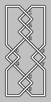
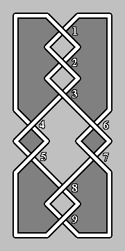
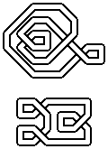
The
link
diagrams
in
Fig. 3,
for
example,
are
distinct
(consider
the
number
of
crossings
in
each
which
may
be
removed
by
a
type
I
Reidemeister
move)
but
have
the
same
signed
planar
graphs.
For
this
reason,
the
term
signed
planar
map
is
preferred. In
a
signed
planar
map
corresponding
to
a
connected
link
diagram,
each
edge
in
the
map
corresponds
to
a
crossing
in
the
link
diagram.
An
arbitrary
connected
finite
planar
map
can
be
encoded
using
4
bits
per
edge
[Curtis01a],
so
a
link
diagram
can
be
encoded
using
5
bits
per
crossing
by
converting
it
to
a
signed
planar
map
and
then
appending
sign
bits
for
the
edges
in
some
suitable
order,
e.g.
by
first
occurence
of
each
edge
in
the
counter-clockwise
traversal
of
the
intermediate
tree
described
in
the
encoding
phase. The
link
diagram
can
be
recovered
from
the
encoding
by
recovering
map
as
per
[Curtis01a],
restoring
the
edge
signs
from
the
appended
sign
bits
and
converting
the
signed
planar
map
back
into
a
link
diagram. | |